Service

Home
Service
Company SmartFactory Product Service IR
FAQ
Service Center Download Technical Support FAQ
Smart HMI
Smart HMI Smart SCADA Smart DEVICE Smart Factory Solution
We will do our best to satisfy our customers.
Service Center Download Technical Support FAQ
FAQ
Smart HMI
Q.
[R Series] How to Print the Screen During Operation
Product
A.
For R Series devices, the latest printer drivers no longer support general printers.
Screen printing is only possible when using "an existing compatible printer".
 
※ Note: The latest printer drivers can be used with TOP-PCVIEW and TOP-VIEW after driver installation.
 
1. Connect a Compatible Printer
 - Connect a supported printer directly to the TOP HMI device.
 
2. Access the Printer Settings on the TOP Device
   1) Open the Menu Screen:
      - Pull down the top menu from outside the upper edge of the display.
      - Tap the [Exit] button (first button in the top menu) to open the main menu.
 
   2) If the interface is in Korean, tap the [가] button at the bottom to switch to English ([A]).
 
   3) Navigate to [Control Panel] - [Device] - [Printer].
      - If a compatible printer is detected, its model name will be displayed in the list.
 
 
3. Configure the Print Action in TOP Design Studio
   1) In TOP Design Studio, open the object’s [Effect & Action] settings.
 
   2) In the Action tab, configure the function so that when the specified condition is met, the current full screen is printed.
 
 
[Additional Information – Using a Roll Printer]
For roll printer (mini printer) usage, refer to the setup example provided on the M2I website:
   - Path: Service - Download - Manual/Design - Example Files - How to Set Up a Roll Printer (Mini Printer)
   - Direct Link: https://www.m2i.co.kr/uploaded/board/engexample/d_723168c23c343cb0e00523a907ffe96d0.tds
is the problem solved? View More
Q.
[R Series] How to Capture the Screen During Operation
Product
A.
This guide explains how to capture the currently displayed screen on the HMI while it is in operation.
 
1. Using the Screenshot Menu on the TOP Device
 
Method 1: From the Operation Screen
  1) Pull down the top menu from outside the top edge of the screen.
  2) Tap the Screenshot button.
 
※ Tip: The top menu appears when you drag from the outside of the top screen edge down into the display.
 
 
Method 2: From the Main Menu Screen
  1) Pull down the top menu from outside the top edge of the screen.
  2) Tap the [Exit] button (first button in the top menu) to open the Main Menu.
  3) Select the Screenshot menu option.
 
 
When the screenshot menu is opened, a window will appear.
  1) Select the storage device (System – Internal memory, USB memory, or SD card).
  2) Press the next button to save the current screen as an image.
 
Captured images are saved in the [UserData - ScreenCapture] folder of the selected storage device, with the file name containing the date and time in JPG format.
 
 
2. Calling the Screenshot App Under Certain Conditions
You can create a user-defined button that opens the screenshot menu.
 
  1) In TOP Design Studio, add an object (Rectangle, Ellipse, Image, or Touch object) that supports the Effect & Action settings.
  2) In the object’s [Action] tab, set: [Special] - [App] - [ScreenShotCall].
  3) When the condition set for this object is met, the screenshot menu will open, allowing the user to capture the screen.
 
3. Capturing and Saving the Screen Automatically Based on Conditions
You can also configure the device to capture the screen automatically—without displaying the screenshot menu—whenever a certain condition is met.
 
  1) In TOP Design Studio, add an object (Rectangle, Ellipse, Image, or Touch object) that supports the Effect & Action settings.
  2) In the object’s [Action] tab, set: [Special] - [Screen] - [ScreenShot].
  3) Specify the storage location (System – Internal memory, USB memory, or SD card).
 
When the set condition is met, the current screen will be captured immediately and saved to the selected storage location.
is the problem solved? View More
Q.
[XTOP Series] How to Capture or Print the Screen During Operation
Product
A.
This guide explains how to capture or print the currently displayed screen on XTOP devices while they are in operation.
 
1. How to Capture the Screen
You can save a screenshot of the current screen to a USB memory stick connected to the XTOP device.
 
Steps:
   1) Insert a USB memory stick into the XTOP device.
   2) Create a touch tag (button object) on the screen.
   3) Go to the tag’s [Operation] page and select [Special Function].
   4) Set the function to: [USB/CF] - [HMI → USB] - [Screen Capture]
 
When the touch button is pressed, the current screen will be captured and saved as an image file to the USB drive.


2. How to Print the Screen
You can print the current screen by connecting a compatible printer directly to the XTOP device.
 
Requirements:
   - A printer that supports HP PCL Level 3.
 
Steps:
  1) Connect the printer to the XTOP device.
  2) Create a touch tag (button object) on the screen.
  3) Go to the tag’s [Operation]  page and select [Special Function].
  4) Set the function to: [PRINT] - [Print Screen]
 
When the touch button is pressed, the current screen will be sent to the connected printer and printed out.
is the problem solved? View More
Q.
[XTOP Series] OS Upgrade via Serial Communication for XTOP07TW-UD / XTOP04TW-UD
Product
A.
This guide explains how to manually upgrade the OS on the XTOP07TW-UD and XTOP04TW-UD models using serial communication.
 
[Overview]
- These models support manual OS upgrades via the COM1 serial port.
- The upgrade process involves updating the OS version to V4.8, which is compatible with XDesignerPlus V4.
- The upgrade consists of sending three files in sequence:
    1. BOOT File
    2. Font File
    3. OS File
 
⚠ Important Notes

- Automatic Upgrade:
This can only be performed via USB communication, by connecting a USB cable to the bottom front port of supported XTOP models.
In this case, you can use the [Transmission] - [BOOT, OS Update] menu in XDesignerPlus V4 for automatic upgrading.
 
- Data Deletion Warning:
Upgrading the OS will erase all project data and settings stored on the XTOP device.
 
- Model Limitation:
The XTOP07TW-UD and XTOP04TW-UD models do not have a built-in USB port.
Therefore, automatic USB-based upgrades are not possible unless you have a dedicated USB-to-COM adapter, which allows USB communication via the COM1 serial port.
This small adapter can be purchased from your local M2I distributor.
 
[Manual Upgrade via Serial Communication]
If you do not have the USB adapter, you must perform the upgrade manually using a serial cable connected to the COM1 port of the XTOP device.
Please refer to the user manual for detailed steps on how to carry out the OS upgrade via serial communication.
is the problem solved? View More
Q.
[R Series] How to Check and Manage Software & TOP HMI Firmware Versions (Upgrade/Downgrade)
Product
A.
This guide explains how to check version information for both the TOP HMI device and TOP Design Studio software, and how version compatibility affects upgrades and downgrades.
 
1. How to Check the TOP HMI Version
  1) Access the Menu Screen on the TOP device.
  2) Tap the [Information] icon → The firmware version will be displayed as shown in the image below.
 

2. How to Check the TOP Design Studio Software Version
  1) Launch TOP Design Studio.
  2) From the top menu, go to [Help] - [About].
 
# If TOP Design Studio is in Korean, you can switch the language to English by going to [View] - [Language].
 
3. When the TOP Design Studio Software Version is Higher than the TOP Device Version
If you try to download a project, the following message will appear:
 
Clicking [Yes] will automatically upgrade the TOP device firmware, and then the project will be downloaded.

4. When the TOP Design Studio Software Software Version is Lower than the TOP Device Version
If you try to download a project, it will be downloaded normally to the TOP device.
In this case, the TOP firmware will automatically downgrade to match the software version.

5. Recommendation
Since the TOP device firmware always adjusts to match the version of TOP Design Studio used, it is strongly recommended to use the latest version of the software to ensure full compatibility and stability.

※ Additional Notes
When opening a project file in TOP Design Studio:
If the project was created with a higher software version than the one currently installed, a message will appear stating that the file cannot be opened.

In this case, you must install a newer version of TOP Design Studio to open the file.

In the Project Wizard window (shown when launching the software or selecting [File] - [New Project]), the Recent Projects List appears.

If a project in this list displays a version number in the top-left corner, it indicates that the file was created in a newer version than the one currently in use.

These files cannot be opened unless the software is updated to the specified version.
 
 
is the problem solved? View More
Q.
[R Series] How to Use the Popup Keypad (Tenkey)
Product
A.
This guide explains how to use the popup keypad feature in TOP Design Studio.

1. Creating a Popup Keypad
When a new project is created in TOP Design Studio, two default keypad windows are automatically generated:
  -. 65534 - Keyboard: Alphanumeric keypad
  -. 65535 - Tenkey: Numeric keypad
 
Default Keypad Types:
  -. 65534 - Keyboard
is used for text input and appears as shown below.
 
  -. 65535 - Tenkey is the default numeric keypad, as shown below.
 
If these windows are accidentally deleted or corrupted, they can be easily re-added:
  -. In the Project Manager, right-click on [Window Screen].
  -. Select [Add Default Tenkey] to add the numeric keypad (65535-Tenkey).
  -. Select [Add String Tenkey] to add the alphanumeric keypad (65534-Keyboard).
 
 
Adding Custom Keypads:
If you want to use a different keypad design, select [Add Library Tenkey] from the same menu.
Choose a keypad from the available list, and click [Add]. The keypad will be created as a new window with the assigned number.
 
※ Note: Library keypad designs are continuously updated.
               For Korean input, the default system-provided keypad is used by the TOP device, and users can customize it as needed.

2. Using the Popup Keypad
Popup keypads can be used with both Numeric Keypad objects and String Keypad objects.
 
For Numeric Keypad Objects:
  1) Open the object property.
  2) Go to the [Input] tab.
  3) Set [Virtual Keyboard] to [POP-UP].
  4) Click the [Select] button next to [Window Number] and choose the keypad window you wish to use.

Popup vs. Fixed Keypad:
  -. Popup Type:
The keypad appears only when data entry is needed. This is ideal for screens with limited space.
  -. Fixed Type: The keypad remains visible on the screen at all times. This may be preferred when screen space is sufficient or when popup behavior is not desired.
 
To use a fixed keypad:
  1) Add the desired keypad screen using [Add Library Tenkey].
  2) Copy the keypad from the newly added window.
  3) Paste it directly into the Base Screen where it should always be displayed.
is the problem solved? View More
Q.
[R Series] Time Synchronization Between TOP and PLC
Product
A.
This guide explains how to synchronize time between the TOP HMI and the PLC.
 
There are two ways to synchronize time:
1. Set the PLC time to the TOP.
2. Set the TOP time to the PLC.
 
You can check and set the current time of the TOP from the bottom of the menu screen.
 
 
The time is stored in the internal special address of the TOP in the format of year, month, day, hour, minute, and second.
 

1. Synchronizing TOP Time Based on PLC Time
To set the TOP time using the PLC time:
1) In TOP Design Studio, go to [Project] - [Property] menu on the top.
2) In the [Project Option] window, select [TOP Setting] on the left list.
3) Open the [Date/Time Sync.] tab on the right side.
4) Check [Use Date/Time Sync.], then configure the [Synchronization condition] and the [Synchronization setting].
-. [Synchronization condition] : Synchronization is performed when the specified condition is met. (e.g., If set as shown below, the sync runs every 12 hours.)
-. [Synchronization setting] : Enter the PLC addresses that store the time (year, month, day, hour, minute, second) in the corresponding fields.
 
 
2. Synchronizing PLC Time Based on TOP Time
To set the PLC time using the TOP time:
-. The date and time (year, month, day, hour, minute, second) stored in the TOP’s special address must be written to the PLC time address.
-. This is done using a Global Script in TOP Design Studio.
-. Global Script run continuously regardless of the currently displayed screen, as long as the specified condition is met.
 
-. As shown below, set the script condition to run at 9:00 and 21:00 (9:00 PM), ensuring synchronization occurs every 12 hours.
 

-. The script content should copy the values from the TOP’s special time addresses to the corresponding PLC time addresses.

※ Note
-. The TOPR/RX/RW/RE/RH series includes a built-in soldered battery on the main board.
-. This battery is used only for the internal clock.
-. If the battery fails, the time resets to 2000-01-01 on the menu screen.
-. In such cases, please contact our customer support center for service.
 
is the problem solved? View More
Q.
[R Product] Please tell me the products where cameras can be attached
Product
A.
You can create a safer industrial environment by attaching various cameras to the TOP, checking video while working, or saving necessary video.
 

[Types of Cameras]
You can attach USB cameras, IP cameras, video cameras, thermal cameras, and so on.
 
1. TOPR Premium models have a built-in camera at the top center of the front.
2. USB camera: camera attached to the USB port of the TOP
3. IP camera: camera attached to the Ethernet port of the TOP
4. Video camera: camera attached to the Video port of the TOP
5. Thermal camera: a thermal camera that expresses temperature, attached to the Ethernet port of the TOP
 
 
[Models that can attach cameras]
1. TOPR Premium models: built-in front camera, video camera, USB camera, IP camera, thermal camera supported
  - Display units: TOPRD1520X, TOPRD1220X, TOPRD1020S, TOPRD0820S
  - Process units: TOPRP20D
 
2. TOPR Standard models: USB camera, IP camera, thermal camera supported
  - Display units: TOPRD1510X, TOPRD1210S, TOPRD1010S, TOPRD0810S
  - Process units: TOPRP10D
 
3. TOPRX models: thermal camera supported
   - TOPRX1500XD, TOPRX1200XD, TOPRX1200SD, TOPRX1000SD, TOPRX1000VD, TOPRX0800SD, TOPRX0800VD, TOPRX0500VD
 
 
[Camera Video Display]
By registering a camera/thermal camera object, you can display/save video.

1. By registering a camera object, you can display the video from built-in front/video/USB/IP cameras on the screen.
  - Cam: Built-in front camera of TOPR Premium model
  - CCTV: Video camera attached to the VIDEO port of TOPR Premium model
  - USB external camera: USB camera
  - IP external camera: IP camera
 
Only one camera object can be registered per screen.
That means basically only one camera video can be displayed per screen.
However, if the registered camera object is an IP camera, you can additionally display one more camera video from other cameras (USB/video/front camera).
 
2. Using thermal camera objects, you can display temperature visualization video from thermal cameras on the TOP screen.
Up to four thermal cameras can be attached and displayed on the screen.
 
---------------------------------------------------------------
 
[Camera Video Recording]
 
Camera video can be stored in TOP device memory, USB memory, SD memory, or the option module TOPR_OPT_CAM32 memory.
 
  - For video storage media, SD memory or the option module TOPR_OPT_CAM32 is recommended over the TOP device memory.
 
Register on the camera object’s [Key] page as below. Press the [Record Start] key to start recording, and press [Record End] to stop recording.
[Snap Shot] captures the video and saves it as an image.
 
 
Storage media is controlled on the camera object’s [Camera] page.
If [Use Storage Media]-[SD Card] is checked, recording is saved to SD memory or TOPR_OPT_CAM32 memory; if unchecked, it’s saved to the TOP device memory.
 
SD memory and TOPR_OPT_CAM32 memory (option module) cannot be used simultaneously.
On the TOP device menu screen under [Control Panel]-[SD Card], select which memory to use as follows:
If camera object storage media is set to SD Card, and [Camera Data] is set to SD_Card1, video is saved to the SD card inserted in the SD slot, and if set to EXT_Cam32, video is saved to the option module TOPR_OPT_CAM32 memory attached to the EXT port.
 
To store video on USB memory, instead of using the camera object’s [Record Start] key, create a separate switch registered under [Effect and Action] page as [Special] - [Camera] - [Camera Record Start] and set the save location to USB.
 
 
Camera video and screenshot files saved on the TOP device can be copied or moved to USB memory.
 
When USB memory is attached to TOP, USB menu appears on screen.
Execute [Cam Capture/Cam Movie] in the USB menu.
If USB menu is closed, press the [USB] button in the top menu to reopen.
 
[Cam Capture] copies camera screenshot data to USB memory.
[Copy All] copies and moves data; [Move All] cuts and moves data.
 
[Cam Movie] copies camera video data to USB memory.
[Copy All] copies and moves data; [Move All] cuts and moves data.
 
This is a direct English translation of the detailed explanation about camera types, models, video display, recording, and USB saving for the R product TOP system.z
is the problem solved? View More
Q.
[R Product] How to Search for PLC Addresses Used in a Project
Function/Development
A.

We will guide you on how to check the addresses used in the TOP project file.

Open the TOP project file in TOP Design Studio.
Execute [Tool]-[Cross Reference] from the top menu.


  1. Enter Search Conditions

When you run the [Address/Object Search] menu, the following screen appears.
To search addresses, select the [Address] tab under the top [Object/Address] tab.

[Location] means the search location (scope).
- ALL means entire project,
- ALL Screen means all screens,
- ALL Global means all global areas (recipes/alerts/logs, etc.).
To search the entire project, select [ALL], or to narrow the scope to specific screen(s), select the specific screen.


[Object] means which objects to search: select [ALL] to search all objects, or select a specific object to narrow search.

In [PLC], select the address type to search. To search for PLC addresses, select [PLC1].


[Address Name] is the device name of the address type selected in [PLC].
[Address Keyword] is the address number to search.
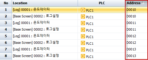
For example, to search address [D0010], select [D] for the Address Name and enter  as the keyword.


2. Display Search Results

After input, press the [Search] button at the top, and the results are displayed in lists.

There are an upper list and a lower list.

The upper list is sorted by [Location] order — global areas (recipes-alerts-logs) are displayed first, then by screen.
You can change this sorting by clicking the headers of the list.
Clicking the [Address] header sorts addresses sequentially, toggling ascending/descending order with the small arrow each click.


The lower list shows the objects and global areas using the address selected from the upper list.

Double-clicking a list item in either list opens the property window of the object using the address. If it is a global address, the global setting window opens.

If you want to save the search results to an Excel file, press the [Export to Excel] button at the top.


#Note: To see the addresses used at a glance on a single screen rather than search, use the [Hint] feature in TOP Design Studio’s top [View] menu.

Set the hint to [Always Show] and content to [All Address], and the addresses used by each object are shown at the top-left of each object on the screen, allowing easy viewing of all addresses at once.

This concludes the direct English translation of the instructions for searching PLC addresses used in the R product TOP project.


is the problem solved? View More
Q.
[R Product] How to Adjust Window Screen Size
Function/Development
A.

How to Adjust the Window Screen Size

The window screen is a screen that is called and used as needed from the main screen. It is mainly used by adjusting the size according to the composition of registered objects rather than popping up (calling) the entire screen area.


      1. Automatic Adjustment of Window Screen Size

After finishing editing the window screen, right-click on the window screen, and a menu like the picture below will appear.
If you execute the [Auto Adjust Window Screen Size] menu, the window screen size changes to the outer boundary that includes all registered objects on the window screen.


     2.Manual Adjustment of Window Screen Size

To adjust the size, open the window screen and run the [Screen] menu at the top.
You can see the [Screen Size] section where you can check the current [Width] and [Height] of the window screen.
Enter the [Width] and [Height] you want to adjust, then press the [Change] button.


A message box will appear asking whether you want to automatically resize the objects registered in the window screen to fit the new window screen size.
If you press [Yes], the sizes of the objects will be changed to fit the resized window screen.
If you press [No], the sizes of the objects will not be changed, and only the window screen size will be changed.

The window screen size can be changed not only from the top [Screen] menu but also in the window screen’s [Properties] pane.
As shown in the picture below, to change the window screen size in [Project Management], select the window screen, right-click to open the menu, and the [Properties] menu will appear.

When you execute the [Properties] menu, the [Window Properties] window for the selected window screen will appear.
In the [Window Properties] window, you can change the [Width] and [Height] under [Window Size Settings].

This is the literal translation of your provided Korean text on how to adjust the window screen size.

is the problem solved? View More
1 2 3 4 5

This site is not supported by the current browser. Please download and use another browser below.