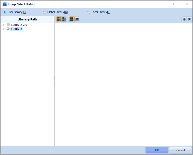
You can see the full service provided by M2I.
Software
Catalog
Certificate
Manual/Design
To copy to USB memory manually:
Attach the USB memory to TOP or press the [USB] button in the top menu on the RUN screen to open the USB menu.
After pressing the [Global Data] button, the [Log Upload/Alarm Upload] button will appear below.
Click [Alarm Upload], and the [Select Path] screen will appear, where you can set the save path for the alarm file. Clicking [OK] will start the upload process.
When complete, the alarm data will be saved in CSV format on the USB memory. The CSV file can be opened with Excel or a standard editor (like Notepad).
To copy automatically according to set conditions:
※ This function is supported from TOP Design Studio V1.4.10 and above.
Register an object (Image/Touch/Rectangle/Arithmetic, etc.) with an [Effects and Operation] page.
Set the [Operation] - [Special] - [System] - [Alarm CSV Export] and choose [USB] as the save location.
Whenever the set condition is met, alarm data is copied to the USB memory. The alarm data is stored as a CSV file by date. The file name format is [2019-07-04 (the date of the alarm data)_A01 (Group ID)_ALARM.CSV].
To copy an alarm file backed up on an SD card to a USB memory:
You can use the file explorer to copy alarm files backed up on the SD card to a USB memory, as shown in the diagram. Start the file explorer from the TOP main menu [File Browser], or on the TOP run screen by clicking the [Browser] button.
Mount the USB memory onto the TOP main unit.
Press the [Memory] button at the top left to switch to SD card mode.
In the SD card's [HMIAlarmBlock1 (block number)] folder, select the alarm files (.CSV). To select multiple files, press the [Select] button, then select each file you wish to copy in order. Press [Copy] to copy.
Press the [Memory] button again to switch to USB memory mode.
After selecting the folder to paste into, press the [Paste] button to complete the copying process.
The memory used to store data such as logs, alarms, and recipes is backup memory.
This memory is fixed at 512KB and the total capacity cannot be changed.
Within the 512KB, you can allocate memory to logs, alarms, and recipes as needed.
Run the [Project] - [Properties] menu to open the [Project Options] screen.
In [TOP Settings] - [Project Options] - [Partition Settings], you can adjust the memory allocation for logs, alarms, and recipes.
Check the required sizes in the [Log], [Alarm], and [Recipe] settings under the [Project] menu and ensure that the allocation in Partition Settings is sufficient.
For TOPRE0400WD / TOPRE0400WD NE / TOPRE0700WD / TOPRE0700WD NE (TOPRE Series) products, there is only one COM port physically visible. However, this port is separated into COM1/COM2 in the software.
Pins 2, 3, and 5 of the serial COM port are used for COM1 RS-232C communication,
while pins 1, 4, 6, and 9 of the same serial COM port are used for COM2 RS422/485 communication.
Previous models (XTOP04TW-UD / XTOP07TW-LD / XTOP07TW-LD-E / XTOP07TW-UD) provided two COM ports: COM1 communicated only with RS-232C, and COM2 supported RS-232C/422/485 communication.
If you previously set up RS-232C communication with the PLC on COM2 and transfer the same project file directly to a TOPRE Series device, communication will not work due to a change in the port configuration. This is because the COM2 port of the TOPRE Series does not support RS-232C communication.
In this case, proceed as follows:
Launch the [Project - Properties] menu in TOP Design Studio.
In [Project Options], move the PLC configured on COM2 to the COM1 port.
Select the PLC for COM2 with your mouse and drag & drop it to COM1.
Transfer the project file again.
After moving to the menu screen using the Exit button in the top menu of TOP, go to [Control Panel - Serial] and match the COM1 communication settings to the PLC settings.
Run the [Control Panel - PLC] menu and press the [Communication Diagnostics] button at the bottom to check if communication succeeds.
You can see the full service provided by M2I.