
You can see the full service provided by M2I.
The function of attaching a USB memory to TOP and retrieving log data stored inside the TOP device is called [Log Upload]. This is different from SD card backup. Backup means copying log data stored in the TOP device and then deleting the backed-up log data from the TOP device, whereas upload means copying the log data without deleting it. USB memory cannot be used for backup, only for upload (copy).
When a USB memory is attached to TOP, the following menu appears on the TOP screen.
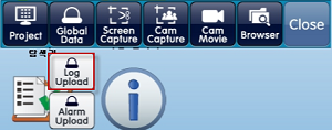
Press the [Global Data]-[Log Upload] button and a [Select Path] window will appear.
In the [Select Path] window, set the USB path where the uploaded log data will be saved.
When you press the [OK] button, the log data stored in TOP will be copied to the USB memory, creating CSV files organized by the date of the log data. The selected USB memory path will have a [LoggingLOG_1] folder generated, and inside this folder, files will be saved with file names in the format: [2019-07-04(date of log data)_LOG001(log number)_000000(file number).CSV].
If a folder with the same name or CSV files with the same date already exist in the selected path, a [Copy Warning] window will appear, allowing you to select the handling method for duplicate files: [Skip / Overwrite / Save As / Cancel], etc.
While TOP is running, if you want to upload logs to the USB memory without removing and reinserting the USB memory, you can execute the [Top Menu]-[USB] menu to open the above menu.
The top menu can be accessed by pulling down from the top edge outside the screen into the screen area.
2. Automatically Uploading to USB Memory Using Conditions
Register an object (such as image, touch, rectangle, arithmetic, etc.) that has the [Effect and Action] page.
Set the object’s [Action]-[Special]-[System]-[Logging CSV Export], then set the save location to [USB].
Whenever the condition is met, the log data is copied to the USB memory and saved as daily CSV files. The file name format is: [2019-07-04(date of log data)_LOG001(log number)_000000(file number).CSV].
3. Copying Log Files Backed Up on SD Card to USB Memory
You can copy log files backed up on an SD card to USB memory using the file explorer as shown below.
Open the file explorer by executing [File Browser] from the TOP device menu screen or by pressing the [Browser] button on the top menu of the TOP operation screen.
Attach the USB memory to the TOP device.
Press the [Memory] button on the upper left to switch to the SD card icon mode.
Select the log files (.CSV) located in the SD card’s [HMILoggingLOG_1(LogID)] folder.
If you want to select multiple log files, press the [Select] button and sequentially choose the files to copy.
Press the [Copy] button to copy the selected files.
Press the [Memory] button again to switch to the USB memory icon mode.
After selecting the folder you want to paste into, press the [Paste] button to complete copying.
Note) Uploading Logs to PC ---------------------------------------
Connect the TOP device and PC via USB cable or Ethernet cable.
Run the [Transfer]-[Data Upload] menu in TOP Design Studio.
In the [Upload] screen, set it to [Log], input the log information you want to upload, then specify the path using the [Select Folder] button.
Press the [Upload] button to start uploading log data. Log files in CSV format are generated on the PC at the specified path organized by date.
File names follow the format: [2019-07-04(date of log data)_LOG001(log number)_000000(file number).CSV].
We will guide you on how to back up log data stored in TOP to an SD card.
#For how to set up the log function, refer to the attached sample project file.
The TOP device's backup memory is memory that stores data such as logs/alerts/recipes.
This memory is fixed at 512KB and cannot be changed.
Of this, the amount of memory usable for logs can be set in [Project]-[Properties] menu, which appears in the [Project Options] screen under [TOP Settings]-[Project Options]-[Partition Settings]. You can adjust this appropriately depending on the amount of log/alert/recipe data used in your project.
To store more data than the device-provided memory allows, you can equip an SD card or the optional module TOPR_OPT_CAM32 (for TOPR only) to back up data.
#The optional module TOPR_OPT_CAM32 can be found on the homepage under [Product Intro]-[Cables & Components].
[Backup Settings]
The backup function is set in the [Project]-[Log]-[Backup] page in TOP Design Studio.
Setting [Storage Medium] and [Old Log File Delete Unit]
Set [Storage Medium] to [SD Card/Ext Cam32] as above, and set [Old Log File Delete Unit] to 30%.
When the log data is full to the [Log Count], it copies 30% of the oldest log data and backs it up as a CSV file on the SD card. You can open the CSV file in Excel to check it. After backup, the backed up log data is deleted from the TOP device. #Log Count is set on the [Log Address] page as shown below.
If the log count is 1,000 and the log data in the TOP device is full with 1,000 logs, it copies 30% (300 logs) of the oldest log data and backs it up as a CSV file on the SD card. Separate files are created depending on the date and Log ID of the stored log data. After backup, the backed up log data is deleted from the TOP device.
The log files created on the SD card are stored in the [HMILoggingLOG_1(LogID)] directory.
#Notes --------------------------------------------------------
If [Storage Medium] is set to [None], no backup will be made. When [None] is set, settings below storage medium are meaningless.
#Cautions --------------------------------------------------------
1. If backup is triggered when the log data reaches the [Log Count] but there is no SD card inserted, backup will not happen and [the percentage set in Old Log File Delete Unit]% of the log data in the main unit will be deleted, so caution is required.
2. [Old Log File Delete Unit] also applies to the SD card capacity. If the capacity of the inserted SD card is full, [the percentage set in Old Log File Delete Unit]% of the oldest files on the SD card will be deleted.
2. Setting [Backup Condition] (Related to creating a CSV file on the SD card simultaneously with backup)
[Backup Condition] is an additional condition that triggers a backup, separate from the backup that happens when the log data reaches the log count. You must set at least one of [Use Backup Condition] or [Backup on Log File Name Change]. By default, [Backup on Log File Name Change] is enabled.
When a backup is triggered by a [Backup Condition], regardless of the [Old Log File Delete Unit], all log data in the TOP device is copied and backed up to the SD card, and the backed up log data is then deleted from the device.
If you set [Use Backup Condition], every time the set condition is met, the entire log is backed up. Even if there is already a CSV file for the same date, a new CSV file is created for each backup, incrementing the file number by 1. [2019-07-03_LOG001_000001(CSV file number +1).CSV]. Each time backup occurs, a new CSV file is created.
[Use Backup Condition] is used when you want to back up the entire log under a certain condition and save it in a separate file.
#If you want to back up the entire log using a specific condition but record it continuously in the same daily CSV file (not a new file), use [Object]-[Action and Effect]-[SD Update] function.
[Backup on Log File Name Change]: Every time the file name parameter of the CSV file to be stored on the SD card changes, a full backup occurs. The file name is normally [Date (YYYY-MM-DD)_LogID_FileNumber (000000 incremented) .CSV]; so, when the date changes (midnight), the full backup is executed.
Assuming backup runs normally at 12AM every day, as of July 4, 2019 at 12AM, log data accumulated for one day (July 3, 2019) will be in the device. That data will be backed up to a file named [2019-07-03_LOG001_000000.CSV].
Suppose the TOP unit was turned off or there was no SD card for three days from July 1 to July 3 and no backup occurred; if, on July 4, all 300 logs are backed up, SD card will have three files: [2019-07-01_LOG001_000000.CSV], [2019-07-02_LOG001_000000.CSV], [2019-07-03_LOG001_000000.CSV].
After July 4 midnight, if the log data fills up and triggers backup for [Old Log File Delete Unit]%, [2019-07-04_LOG001_000000.CSV] is created. Every time backup is triggered due to logs filling up, logs are written continuously in the CSV file for that date. In summary, the SD card will have one CSV log file per day.
#[Backup on Log File Name Change] and [Split Save] are described in item 3 below.
3. [Log File Name Option] setting (related to CSV file name on SD card)
CSV file names saved on the SD card may differ by the [Log File Name Option] setting, but basically are saved as [Date (YYYY-MM-DD)_LogID_FileNumber (starts at 000000 and increments).CSV], for example, 2019-07-03_LOG001_000000.CSV.
If you enable [User Defined Name] and [HMI Alias], file names become [Date_LogID_FileNumber_HMI Alias_User Defined Name.CSV]. #The HMI alias is under the [Information] menu of the TOP device. This helps identify which TOP’s log data was backed up, when using a single SD card with multiple TOPs.
If you set [Split Save], the file name becomes [Date_LogID_FileNumber_HMI Alias_User Defined Name_Split Save Address.CSV]. This function, together with [Backup on Log File Name Change], allows you to perform a full backup every time the address set in [Split Save] changes. Even if there are files for the same date, a new CSV file is created each time, with the address (number/text) appended to the file name. This is used when you want to back up when the address value (such as process, model, etc.) changes and record that value in the file name.
[SD Update operation] --------------------------------------------------
If you want to back up all log data remaining in the TOP device to the SD card when removing an inserted SD card, use the [Object]-[Action and Effect]-[Action]-[Special]-[Storage]-[SD Update] function.
All logs in the TOP device are backed up. CSV files are created by date of log data. If an identical date CSV file already exists on the SD card, data is appended rather than a new file being created.
[SD Card Specifications] ---------------------------------------------------
It is recommended to use an SD card of 32GB or less, formatted as FAT32.
[Summary] ----------------------------------------------------------
1. Note that backup means copying log data from the TOP device and saving it to the SD card, then deleting the backed up log data from the device.
2. To back up log data by date, use [Backup on Log File Name Change] without [Old Log File Delete Unit] or [Split Save]. To manually back up all logs, use the SD Update function.
3. To create multiple CSV files even for the same date, use [Use Backup Condition] or [Backup on Log File Name Change] + [Split Save] settings.
1. To copy to USB memory manually:
Attach the USB memory to TOP or press the [USB] button in the top menu on the RUN screen to open the USB menu.
After pressing the [Global Data] button, the [Log Upload/Alarm Upload] button will appear below.
Click [Alarm Upload], and the [Select Path] screen will appear, where you can set the save path for the alarm file. Clicking [OK] will start the upload process.
When complete, the alarm data will be saved in CSV format on the USB memory. The CSV file can be opened with Excel or a standard editor (like Notepad).
2. To copy automatically according to set conditions:
※ This function is supported from TOP Design Studio V1.4.10 and above.
Register an object (Image/Touch/Rectangle/Arithmetic, etc.) with an [Effects and Operation] page.
Set the [Operation] - [Special] - [System] - [Alarm CSV Export] and choose [USB] as the save location.
Whenever the set condition is met, alarm data is copied to the USB memory. The alarm data is stored as a CSV file by date. The file name format is [2019-07-04 (the date of the alarm data)_A01 (Group ID)_ALARM.CSV].
3. To copy an alarm file backed up on an SD card to a USB memory:
You can use the file explorer to copy alarm files backed up on the SD card to a USB memory, as shown in the diagram. Start the file explorer from the TOP main menu [File Browser], or on the TOP run screen by clicking the [Browser] button.
4. Mount the USB memory onto the TOP main unit.
Press the [Memory] button at the top left to switch to SD card mode.
In the SD card's [HMIAlarmBlock1 (block number)] folder, select the alarm files (.CSV). To select multiple files, press the [Select] button, then select each file you wish to copy in order. Press [Copy] to copy.
Press the [Memory] button again to switch to USB memory mode.
After selecting the folder to paste into, press the [Paste] button to complete the copying process.
The memory used to store data such as logs, alarms, and recipes is backup memory.
This memory is fixed at 512KB and the total capacity cannot be changed.
Within the 512KB, you can allocate memory to logs, alarms, and recipes as needed.
Run the [Project] - [Properties] menu to open the [Project Options] screen.
In [TOP Settings] - [Project Options] - [Partition Settings], you can adjust the memory allocation for logs, alarms, and recipes.
Check the required sizes in the [Log], [Alarm], and [Recipe] settings under the [Project] menu and ensure that the allocation in Partition Settings is sufficient.
For TOPRE0400WD / TOPRE0400WD NE / TOPRE0700WD / TOPRE0700WD NE (TOPRE Series) products, there is only one COM port physically visible. However, this port is separated into COM1/COM2 in the software.
Pins 2, 3, and 5 of the serial COM port are used for COM1 RS-232C communication,
while pins 1, 4, 6, and 9 of the same serial COM port are used for COM2 RS422/485 communication.
Previous models (XTOP04TW-UD / XTOP07TW-LD / XTOP07TW-LD-E / XTOP07TW-UD) provided two COM ports: COM1 communicated only with RS-232C, and COM2 supported RS-232C/422/485 communication.
If you previously set up RS-232C communication with the PLC on COM2 and transfer the same project file directly to a TOPRE Series device, communication will not work due to a change in the port configuration. This is because the COM2 port of the TOPRE Series does not support RS-232C communication.
In this case, proceed as follows:
1. Launch the [Project - Properties] menu in TOP Design Studio.
In [Project Options], move the PLC configured on COM2 to the COM1 port.
Select the PLC for COM2 with your mouse and drag & drop it to COM1.
Transfer the project file again.
2. After moving to the menu screen using the Exit button in the top menu of TOP, go to [Control Panel - Serial] and match the COM1 communication settings to the PLC settings.
Run the [Control Panel - PLC] menu and press the [Communication Diagnostics] button at the bottom to check if communication succeeds.
If the PLC is set to COM2 in the project file, you need to open the project file on your PC, change the setting to COM1, and then transfer it to TOP.
Run the [Project] - [Properties] menu; the [Project Options] screen will appear.
On the left side, under [Device Setup], you will see the PLC set to the COM2 port.
To move this PLC to COM1, click on the PLC and drag & drop it to [COM1].
You can see the full service provided by M2I.