Service

Home
Service
Company SmartFactory Product Service IR
FAQ
Service Center Download Technical Support FAQ
Smart HMI
Smart HMI Smart SCADA Smart DEVICE Smart Factory Solution
We will do our best to satisfy our customers.
Service Center Download Technical Support FAQ
FAQ
Smart HMI
Q.
How to Change the Menu Language to English
Product
A.
The menu (Setup screen) supports both Korean and English.
 
1. XTOP Models
On the menu screen, tap the [가] button at the bottom right corner.
It will switch to [A], and the menu will display in English.
To switch back to Korean, tap [A] again to return to [가].
 
2. TOPR / TOPRX / TOPRW / TOPRH / TOPVIEW Models
On the menu screen, tap the [가] button at the bottom right corner.
It will change to [A], and the menu will switch to English.
Tap [A] again to revert to [가] and display the menu in Korean.
 
is the problem solved? View More
Q.
[XTOP] Where Do I Configure Communication Settings? (For Product Replacement)
Communication
A.
When replacing the product with a new unit, you can generally use the same project file and cable. In most cases, only the communication settings need to be checked.
 
On the previous device, go to the menu and select [PLC Setup] - [HMI COM2 Setup] to check the following communication parameters:
[Baud Rate / Data Bit / Stop Bit / Parity Bit / Signal Level].
Enter these same settings into the new device.
 
 
Note: If the new product is an R Series model, go to [Control Panel] - [Serial] in the menu to access the communication settings screen shown below.
If the previous device is unavailable and you cannot retrieve its communication settings, check the PLC’s communication configuration via the PLC program.
You can then apply the same settings in TOP.
For more detailed instructions, please refer to the communication manual of the specific PLC.
 
is the problem solved? View More
Q.
[XTOP] XDesignerPlus Text Appears Very Small
Software
A.
If, after installing XDesignerPlus on your PC and launching the program, the text in the left [Project Manager] appears very small, please follow these steps:
 
XDesignerPlus supports displaying in various languages such as English, Korean, and Chinese. To ensure compatibility with all languages, it uses the [Arial Unicode MS] font, which can display characters from most languages.
If this font is not supported on your PC, the issue you are experiencing may occur.
 
1. Check if the [Arial Unicode MS] font is present in your PC's [C:WindowsFonts] folder.
2. If the [Arial Unicode MS] font is disabled, right-click on it and select [Show] from the context menu to enable it.
3. If the [Arial Unicode MS] font is not present, download it and place it in the [C:WindowsFonts] folder.
4. Restart XDesignerPlus. The text in the Project Manager should now display correctly.
 
is the problem solved? View More
Q.
[Product Fault Diagnosis] When the Front Touch Sensor Glass is Broken Due to Impact
Product
A.
1. If the LCD screen displays normally after turning on the product, only the front Touch ASS’Y (touch sensor + front sheet + front case) needs to be replaced for repair.

2. If the LCD screen does not display normally, both the front Touch ASS’Y (touch sensor + front sheet + front case) and the LCD panel must be replaced for repair.
is the problem solved? View More
Q.
[R Product Fault Diagnosis] How to Diagnose COM2 RS-232C Port
Product
A.
1. Short pins 2 and 3 of the COM1/COM2 connector using a clip or similar tool, then enter the [Control Panel] from the [Menu Screen].
2. In the [Control Panel] menu, select the [Serial] menu.
3. In the serial window, select the signal level as RS-232C and run [Port Diagnosis].
4. A serial self-diagnosis window will pop up. If it displays [COM2, RS-232C: Communication, OK], the port is normal.
5. If, despite a proper short, it displays [COM2, RS-232C: Communication, Error], this indicates a hardware issue with the port. Please request A/S support from the customer service center.
 
Note:
Port diagnosis is different from [PLC Communication Diagnosis]. Port diagnosis is also called a loopback test and is used to check whether the hardware port is normal or faulty.
Communication diagnosis can be performed in the [Control Panel-PLC] menu on the menu screen.
For PLC communication, please refer to the relevant manual for cable wiring diagrams and communication settings.
is the problem solved? View More
Q.
[R Series] Project File (Screen Data) Upload/Download Method
File transfer
A.

- Upload
1. Connect the communication cable between the TOP and PC.
- Connect the USB cable to the USB device port on the main unit (usually the front USB port).
- If using an Ethernet cable, connect it to the TOP.
2. Run TOP Design Studio, then select [Data Upload] under the [Transfer] menu.
3. When the [Connection Settings] window appears, select the cable you are using (Ethernet or USB; default is USB).
 - Click the [Connect] button.
 - If the TOP’s information appears in the [Connection Information] field on the right, the connection is successful.
 - Click the [OK] button to open the [Upload] window.
4. At the bottom, you will see options for 0 project, 0 log, and 0 alarm.
- Check the project box, set the save path using the [Select Folder] button, and click the [Upload] button to begin the upload.
 
- Download
1. You can transfer files using USB communication via the front OTG port.
- For products that support Ethernet, file transfer is also possible via Ethernet communication.
2. Use TOP Design Studio. The project file extension is [.TDS].
- Open the project file and select [Full Build & Transfer] under the [Transfer] menu.
3. Project build will proceed, and the connection settings window will appear.
- Select the cable you are using (Ethernet or USB), click the [Connect] button (check the connection information on the right), then click the [OK] button at the bottom right.
4. In the project build window, select the [Transfer] menu at the top to begin the transfer.
is the problem solved? View More
Q.
[XTOP] How to downgrade XTOP OS from V4.8 to V3.1
Product
A.
To downgrade, you need to transfer the files in the following order:
V3.1 Boot file → Font file → OS file.
Please download the attached file from the 5th post in the [Service] - [Download] - [Manuals/Design] - [Other Materials] section of our homepage, and follow the instructions provided in the  manuaL.
is the problem solved? View More
Q.
[XTOP] Communication Fails After Uploading a Modified Project
Communication
A.
If you are using the same PLC and communication cable, but communication fails after uploading a modified project, it's likely that the communication settings have changed from the previous configuration.
 
1. On the XTOP device, go to the menu screen and check the [Comm. Setup].
 
2. In XDesignerPlus V4, go to [Project] - [Project property] menu.
Select the TOP Model name in TOP Setting from the left panel. On the right side, and check the [Use HMI Setup] option.
If this option is checked, the settings on the XTOP device will be overwritten by the values defined in [Use HMI Setup] during the project transfer.
 
After adjusting the communication settings correctly, run the Communication Diagnosis to verify if the connection is successful.
is the problem solved? View More
Q.
[XTOP] How to Check Communication Status Between TOP and PLC
Communication
A.
You can verify whether communication between the TOP device and the PLC is functioning properly by using the [Communication diagnostics] Button on the TOP device’s menu screen.
 
• For OS Version V3.1
From the XTOP device, enter the menu screen and navigate to the [Diagnosis] page.
If the screen appears in Korean, press the [가] button at the bottom to switch to English (toggle).
Communication diagnostics are found under item No. 5, 6, and 7. Run the appropriate Diagnosis based on the port connected to the PLC.
 
• For OS Version V4.8
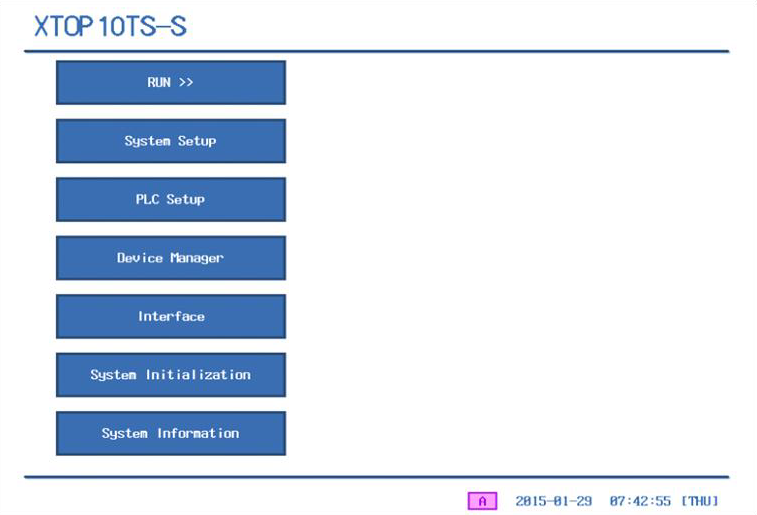
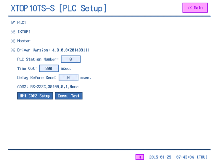
From the XTOP device, enter the menu screen and press the [PLC Setup] button.
If the screen appears in Korean, press the [가] button at the bottom to switch to English (toggle).
Then press the [Comm. Test] button at the bottom of the screen.
 
TX represents the transmit protocol, which sends data from the TOP device to the PLC, while RX represents the response protocol, which receive data from the PLC to the TOP device.
The communication result is displayed in item No. 3.
 
If the result shows "OK" (Normal), it means the cable and communication settings are correct, and communication is functioning properly.
If the result shows "Error", such as a "Time Out Error", please check the cable connection and communication settings again.
is the problem solved? View More
Q.
How to Install the USB Driver
File transfer
A.
The USB driver is automatically installed during the installation of either XDesignerPlus or TOP Design Studio.
Therefore, no separate USB driver installation is required when connecting via USB cable.
 
However, if you're experiencing USB connection issues when downloading or uploading a project and wish to reinstall the USB driver, you can do so by running the USB Driver Setup.exe located in the software installation directory:
 
[C:Program Files (x86)M2I CorpXDesignerPlus4usb_driver]
[C:Program Files (x86)M2I CorpTOP Design Studiousb_driver]
is the problem solved? View More
6 7 8 9 10

This site is not supported by the current browser. Please download and use another browser below.